
Floodlight schedules that start with wattage are already missing the hardest part of the job. High-mast lighting has to place useful light across a defined surface while controlling glare, spill, shadows, pole loading, and access for maintenance. Identical nominal output can produce very different results when the beam distribution, aiming angle, setback, and target geometry change.
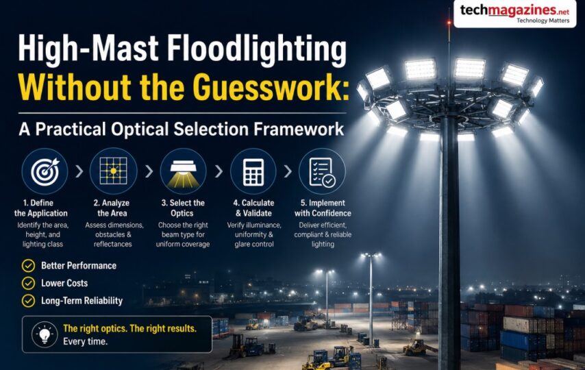
Choosing optics in three layers is the practical alternative: describe the site, match the distribution to its geometry, and verify the complete arrangement with photometric modelling. This framework helps buyers challenge a generic “high power” proposal and gives designers a traceable route from survey data to commissioning measurements.
Layer One: Draw the Lighting Problem Before Naming a Fixture
Start with a scaled plan. Mark the target boundary, pole locations, mounting height above the target plane, setback, obstructions, adjacent property, roads, windows, sensitive habitat, and likely observer positions. Separate areas that perform different tasks. A container yard, loading apron, building façade, and access road may share poles but should not share one undifferentiated target.
For each area, record the maintained average and minimum illuminance required by the applicable project standard, the desired uniformity, operating schedule, and any vertical-light need. Add restrictions such as a property-line limit, a dark boundary, camera performance, or a viewing direction where high source brightness would be unacceptable. These constraints often decide the optic before the wattage.
Survey the environment as well. Coastal salt, airborne dust, heavy rain, vibration, temperature, unstable supply, and cleaning methods affect the enclosure, coating, mounting, driver, and protective system. High ingress ratings are relevant, but they remain one line in the specification rather than a universal certificate of suitability.
Layer Two: Match Distribution to the Shape of the Target
Symmetrical beams spread light around their aiming axis. This approach can work well where a luminaire sits within or near the centre of a broadly regular target. By contrast, an asymmetric beam pushes the useful distribution away from the mounting point and is often better when poles must remain at the edge of a rectangular apron, court, façade, or roadway-like strip. Correct orientation can reduce wasted backlight and excessive tilting.
Coydon Lighting’s KD-FLN series lists symmetrical 15°, 30°, 45°, 60°, and 90° options. Its KD-FLM series includes 10°, 25°, 45°, 60°, and 90° choices plus 65×25° and 130×30° asymmetric beam distributions. These manufacturer-published options give a designer several ways to shape the layout, but the labels alone do not predict the finished result. Exact photometric files must match the ordered models.
Narrow optics are not automatically “long throw,” and asymmetric optics are not automatically low glare. Peak intensity, distribution shape, aiming, source luminance, shielding, and observer location work together. Compare candela data and calculation results, not just a degree label. Where several fixtures overlap, examine both the improved uniformity and the possibility of concentrated hot spots.
Layer Three: Build a Photometric Model That Can Be Audited
Use a current photometric file for every proposed configuration. Model records should state the maintenance factor, surface reflectances, grid spacing, task-plane elevation, terrain or major structures, pole coordinates, mounting height, aiming points, tilt, orientation, and luminaire quantity. DIALux or equivalent software can calculate the layout, but software does not correct inaccurate inputs.
Run more than one scene. Test the proposed layout, a conservative maintenance condition, and at least one credible alternative optic or aiming pattern. Inspect average and minimum values, uniformity, contour plots, vertical illuminance where needed, and light outside the target. If the software offers glare or obtrusive-light metrics relevant to the project, review them with the applicable local limit.
Keep the exported calculation report with a file-revision identifier. Renderings help discussion but cannot substitute for the input schedule and numerical results. When a product is changed during purchasing, rerun the model; do not assume that similar watts or lumens make two photometric files interchangeable.
Use the Three-Layer Optical Selection Framework
Shown below, the Three-Layer Optical Selection Framework links a site condition to a design response and a verification step. It is a decision aid, not a replacement for a qualified lighting design.
Three-Layer Optical Selection Framework
| Observed condition | Candidate response | Model check | Field evidence |
| Pole inside a regular open area | Compare suitable symmetrical distributions and spacing | Check centre intensity, overlap, edge minimum, and uniformity | Grid readings plus aiming and mounting records |
| Pole on the edge of a long target | Compare an asymmetric beam with a tilted symmetrical option | Check forward reach, backlight, glare direction, and far-edge minimum | Target and property-line readings after dark |
| Narrow distant object or façade | Test a controlled narrow distribution with precise aiming | Check hot spot, vertical coverage, aiming tolerance, and spill | Vertical grid and repeatable aiming marks |
| Sensitive boundary behind the pole | Prioritize distribution control, shields, and lower tilt | Calculate backlight and off-site points, not only target lux | Boundary measurements and night photographs |
Turn Product Data Into a Controlled Shortlist
Coydon publishes the KD-FLN and KD-FLM families across a 50W to 1250W range with 85–277V input, CRI 80+, IP66 protection, three listed colour-temperature choices, and 130 lm/W for the series. Coydon also lists a five-year warranty. Treat each value as a family specification to be confirmed for the exact model, optic, driver, controls, and market certification on the quotation.
Shortlist by elimination. Remove configurations that cannot meet the electrical supply, certification, environmental, mounting, or control requirements. Obtain the correct photometric files for those that remain. Then compare designs against one maintained-performance target. Lower-wattage options that need many more poles or create unacceptable spill are not necessarily more efficient at system level.
Buyers reviewing Coydon Lighting should ask for a line-by-line schedule: model code, input power, delivered lumens, distribution code, colour temperature, driver, surge strategy, dimming interface, bracket, weight, projected area, finish, certification, photometric-file revision, and warranty conditions. Attach that schedule to the purchase order so substitutions require written approval.
Control Glare and Spill Before Increasing Output
When a far edge is dark, the intuitive response is to increase output or tilt the luminaire higher. Both can create a new failure: more light above the target, brighter views of the source, and worse conditions outside the boundary. Before adding watts, compare another distribution, change the pole arrangement, lower the tilt, add shielding, or split the task between luminaires.
Define off-site calculation points at windows, roads, property lines, and other sensitive locations. Include likely viewing directions for drivers, security personnel, neighbours, and spectators. Review the installation at night from those positions rather than standing only beneath the pole. If a shield is part of the final solution, include its effect in the model and record its orientation at commissioning.
Colour temperature also affects perception and project constraints even though it does not solve a distribution problem. Coydon lists 3000K, 4500K, and 6000K options for these series. The appropriate choice should consider the task, camera system, surrounding environment, local policy, and stakeholder preference. More bluish light is not a universal proxy for better visibility.
Check Structure, Power, and Maintenance as One System
Every high-mast proposal needs structural review. Confirm bracket capacity, fasteners, pole condition, luminaire weight, projected area, wind conditions, vibration, safety retention, and access method. Photometric success cannot excuse an unsafe mounting arrangement. Responsible engineers should check applicable loads and any effect of replacing a compact legacy head with a larger LED assembly.
Electrically, compare supply voltage, circuit capacity, earthing, protective devices, surge exposure, inrush, switching groups, and control compatibility. Test power-recovery behaviour. If remote controls are used, define what happens after a communication failure and how operators can restore a safe state locally.
Plan maintenance before the mast is occupied by equipment. Keep access routes clear, identify isolation points, label aiming positions, and store spare-driver or spare-luminaire policy with the model codes. A two-person lift, mobile platform, or mast-lowering operation can dominate the cost of a minor component failure. That cost belongs in the selection decision.
Limits, Trade-Offs, and Cases That Need Specialist Review
This framework cannot set the required illuminance or glare limit for every country, sport, roadway, airport, port, or industrial task. Local standards and competent designers must define those values. IP66 does not prove resistance to every chemical, salt environment, immersion condition, pressure-cleaning method, or hazardous atmosphere. Additional testing, coatings, enclosures, or certification may be necessary.
Photometric predictions also have limits. Dirt, ageing, surface reflectance, manufacturing tolerance, voltage, thermal conditions, mounting error, and landscape changes can shift field results. Designs that barely pass every target have no practical tolerance. Use a declared maintenance factor and review sensitivity, but do not hide uncertainty by applying an unexplained blanket margin.
Pause the purchase when pole data is unavailable, the exact photometric file cannot be supplied, an asymmetric beam orientation is unclear, the proposed tilt conflicts with spill limits, or the electrical and structural reviewers disagree. Those are design risks, not paperwork delays. A different mounting arrangement or luminaire family may be the correct outcome.
Commission the Layout Against the Approved Model
- Check model codes, optics, brackets, drivers, and quantities before equipment leaves the ground.
- Record each fixture’s pole, mounting height, circuit, aiming direction, tilt, and shield position.
- Set controls and switching scenes, then test normal operation, override, failure, and power recovery.
- Measure the target grid after dark with the agreed meter and environmental conditions.
- Measure selected boundary, vertical, and observer-position points defined in the design.
- Compare average, minimum, uniformity, spill, and glare-related observations with the approved report.
- Correct aiming or configuration deviations and rerun affected measurements.
- Archive the DIALux report, photometric files, as-built schedule, photos, settings, and readings.
Coydon Lighting publishes project material showing DIALux-led planning for outdoor and industrial lighting applications. Such examples are useful as manufacturer evidence of a design workflow, not as an independent guarantee for a new site. The transferable lesson is the chain of proof: surveyed geometry, named photometric files, recorded assumptions, controlled installation, and field verification.
When that chain remains intact, wattage becomes what it should be—one parameter within a complete optical system. The buyer can then approve a high-mast scheme because its performance and constraints have been tested, not because the fixture has the largest number on the carton. The manufacturer describes high-power floodlights as one of its core product groups; that background supports the shortlist, while the project-specific schedule remains the controlling evidence.