
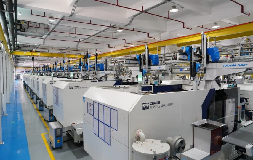

Injection molding remains one of the most widely used manufacturing processes, producing billions of parts annually for industries ranging from automotive to medical devices. Yet even experienced engineers encounter defects that compromise product quality, drive up scrap rates, and inflate production costs. Sink marks, warpage, short shots, and flash are more than cosmetic nuisances—they signal deeper issues in design, tooling, or process control that demand attention.
The challenge lies not in reacting to these problems after they appear, but in preventing them before the first shot is fired. This article provides actionable strategies that engineers can implement to eliminate common injection molding defects at their source. Beyond defect prevention, it explores how energy efficiency improvements and user-focused design principles contribute to consistently high-quality solutions.
By addressing these interconnected factors together, manufacturers can reduce waste, lower operating costs, and deliver parts that meet both functional requirements and end-user expectations with greater reliability.
Understanding Common Injection Molding Defects and Their Impact
Every injection molding operation contends with a predictable set of defects that, left unchecked, erode profitability and product reliability. Understanding these defects—and the mechanisms that produce them—is the first step toward eliminating them from the production floor.
Sink marks appear as depressions on the part surface, typically where wall sections are thicker or ribs intersect with outer walls. They result from uneven cooling and insufficient packing pressure, leaving the material to shrink inward as it solidifies. Warpage distorts the entire part geometry, caused by differential cooling rates, residual stresses, or inconsistent fiber orientation in filled materials. Short shots leave cavities partially unfilled, usually indicating inadequate injection pressure, restricted flow paths, or trapped air that prevents complete mold filling. Flash—thin excess material along parting lines—signals excessive injection pressure, worn tooling, or insufficient clamping force.
These defects do more than affect appearance. Sink marks weaken structural sections. Warped parts fail to assemble correctly, creating downstream quality issues. Short shots produce non-functional components destined for the scrap bin. Flash requires secondary trimming operations that add labor cost and cycle time. Collectively, these problems increase material waste by 5–10% in poorly controlled operations and can push reject rates above acceptable thresholds.
The underlying causes trace back to three interconnected domains: part design decisions made months before production, mold construction and maintenance quality, and real-time process parameter settings. A thick boss without coring invites sink marks regardless of how well the process is tuned. A poorly vented mold produces burn marks no matter how slowly the material is injected. Recognizing this interconnection is essential—effective defect prevention requires addressing all three domains simultaneously rather than chasing symptoms one at a time.
Key Defect Types and Root Causes
Beyond the most visible defects, several others demand attention. Voids—internal bubbles trapped within thick sections—compromise mechanical strength without any visible surface indication. They form when the outer skin solidifies before the core, and shrinkage pulls the material apart internally. Burn marks appear as dark discolorations at flow ends or near venting locations, caused by air trapped and compressed to ignition temperature during rapid filling. Weld lines form where two flow fronts meet and fail to fully bond, creating weak points that fracture under load.
Material factors contribute significantly: hygroscopic resins processed without proper drying develop splay and brittleness. Degraded material from excessive barrel residence time introduces contamination and inconsistent flow behavior. Mold-related causes include inadequate cooling channel placement that creates hot spots, worn or damaged gate inserts that alter flow patterns, and insufficient venting that traps gases. Machine factors such as inconsistent shot size from worn check rings, temperature controller drift, and hydraulic pressure fluctuations introduce variability that manifests as random defects across production runs. Effective defect prevention demands that engineers trace each quality issue to its specific root cause rather than applying generalized corrections, building a systematic understanding that enhances overall quality and process capability over time.
Techniques for Effective Defect Prevention in Injection Molding
Preventing defects requires a disciplined approach that addresses part geometry, tooling quality, and process parameters as an integrated system. Rather than reacting to problems after production begins, engineers who invest time in upfront optimization consistently achieve lower scrap rates and more stable processes. Manufacturers like WEILAN MFG emphasize this integrated methodology, combining design-for-manufacturability principles with rigorous process control to deliver high-quality solutions from the earliest production runs.
Optimizing Part Design for Defect Reduction
Sound part design eliminates the majority of injection molding defects before the mold is ever cut. Maintaining uniform wall thickness throughout the part is the single most effective design strategy—transitions between thick and thin sections should be gradual, with ratios not exceeding 1.5:1 wherever possible. When ribs are necessary for structural reinforcement, their base thickness should remain at 50–60% of the adjoining wall to prevent sink marks on the opposite surface. Draft angles of 1–2 degrees per side facilitate clean ejection and reduce drag marks, while textured surfaces may require additional draft of 1 degree per 0.025 mm of texture depth.
Gate placement directly influences fill patterns, weld line locations, and packing effectiveness. Position gates at the thickest section so material flows from thick to thin, maintaining pressure throughout the fill phase. Avoid gating into areas that face cosmetic scrutiny or experience high mechanical stress. Material selection also plays a critical role in defect prevention—semi-crystalline resins shrink more than amorphous alternatives, demanding tighter process control and more generous draft. Glass-filled materials reduce shrinkage and warpage but introduce challenges with fiber orientation and surface appearance that must be addressed through flow analysis during the design phase.
Process Adjustments and Monitoring
Once design and tooling are finalized, precise process parameter control becomes the primary defense against defects. Injection speed profiling—starting slow to prevent jetting at the gate, accelerating through thin sections, then decelerating near flow ends to reduce air entrapment—addresses multiple defect types simultaneously. Packing pressure and hold time must be calibrated through gate seal studies: gradually increase hold time until part weight stabilizes, indicating the gate has frozen and no additional material can enter the cavity.
Melt temperature should sit in the middle of the resin manufacturer’s recommended range, adjusted only after other parameters are optimized. Cooling time optimization requires balancing part quality against cycle efficiency—too short produces warpage from residual heat, while excessive cooling wastes energy without improving dimensions. Implementing cavity pressure sensors provides real-time visibility into what happens inside the mold during each cycle. These sensors detect variations in fill, pack, and hold phases that external machine sensors cannot capture, enabling automatic rejection of suspect parts and triggering alerts when process drift begins. Statistical process control charting of key parameters—peak cavity pressure, fill time, and cushion position—establishes normal operating windows and identifies trends before they produce defective parts, making defect prevention a continuous rather than reactive discipline.
Enhancing Energy Efficiency for Sustainable Injection Molding
Energy consumption represents one of the largest operating costs in injection molding, typically accounting for 20–30% of total production expenses. Beyond cost implications, inefficient energy use generates excess heat that destabilizes process conditions, contributing directly to defect formation. When hydraulic systems run hot, oil viscosity changes and pressure consistency suffers. When barrel heaters cycle erratically, melt temperature fluctuates and material properties shift from shot to shot. Pursuing energy efficiency therefore serves a dual purpose: it reduces operational costs and environmental footprint while simultaneously creating the stable thermal and mechanical conditions that defect-free production demands.
Modern all-electric and hybrid injection molding machines consume 30–70% less energy than conventional hydraulic systems while delivering superior repeatability. Their servo-driven movements eliminate the continuous energy drain of hydraulic pumps running at full pressure regardless of demand. This precision translates directly into tighter shot-to-shot consistency, fewer rejects, and more predictable cycle times. Heat recovery systems capture waste thermal energy from hydraulic oil coolers and barrel radiation, redirecting it to material drying hoppers or facility heating—turning a loss into productive use. Optimizing cooling circuits with conformal cooling channels and properly sized chillers reduces cooling time while maintaining uniform mold temperatures, simultaneously cutting energy consumption and eliminating warpage caused by thermal gradients. These interconnected improvements demonstrate how energy efficiency and quality are not competing priorities but complementary goals that reinforce each other in well-managed operations.
Practical Steps for Energy Reduction
Implementing energy efficiency improvements begins with measurement. Conduct an energy audit that maps consumption to specific equipment and process phases—plasticizing, injection, holding, cooling, and mold open/close. This baseline reveals where the greatest opportunities exist. Upgrade aging hydraulic machines with variable-speed pump drives or servo-hydraulic systems that match energy output to actual demand rather than running at constant pressure. Replace resistance band heaters with insulating blankets and ceramic infrared heaters that reduce heat loss by up to 40%. Establish preventive maintenance schedules that keep check valves, seals, and heat exchangers operating at peak efficiency—a fouled cooling heat exchanger forces chillers to work harder while delivering inconsistent mold temperatures. Adopt lean manufacturing principles to eliminate unnecessary machine idle time, reduce purge material waste, and streamline mold changeovers so machines spend more time producing good parts and less time consuming energy unproductively. These practical steps deliver measurable energy savings while contributing to the process stability that underpins high-quality solutions across every production run.
Integrating Functional Design and User-Focused Approaches
Defect-free parts that fail to meet end-user needs represent a different kind of waste—one that erodes market position rather than scrap bins. A user-focused design philosophy shifts the engineering conversation from “can we mold this?” to “does this part perform as the user expects?” This mindset naturally reduces defects because parts designed around actual use conditions tend to have more rational geometries, appropriate material choices, and realistic tolerance requirements. When engineers understand how a component will be gripped, loaded, assembled, or exposed to environmental stress, they make design decisions that simultaneously improve manufacturability and user satisfaction.
Aligning part design with end-user requirements means considering ergonomics early—grip surfaces need appropriate texture depth and curvature, snap fits must engage with satisfying tactile feedback without requiring excessive force, and living hinges need flex life that matches actual usage patterns. Durability expectations should drive wall thickness decisions rather than arbitrary standards, ensuring material is placed where stress concentrations actually occur rather than distributed uniformly. Gathering user feedback through field failure analysis, warranty return data, and direct observation of product interaction reveals design weaknesses that traditional engineering analysis might miss. A handle that meets static load requirements but fatigues under cyclic loading patterns typical of real use needs redesign informed by actual user behavior, not just simulation assumptions.
Principles of User-Centered Injection Molding Design
Conducting usability studies before finalizing mold design prevents costly tooling modifications later. Start with rapid prototypes—3D printed or soft-tooled samples—placed in users’ hands to evaluate fit, function, and perceived quality. Observe how people interact with the part without instruction, noting where they struggle or misuse features. Iterate the design based on these observations, refining geometry until the part intuitively communicates its function.
Cross-functional collaboration between industrial designers, mold engineers, and process technicians ensures that user-driven design changes remain manufacturable. A designer might request a complex organic surface for ergonomic reasons, but the mold engineer can suggest alternative geometries that achieve the same hand feel while maintaining uniform wall thickness and adequate draft. This collaborative approach produces parts that satisfy users while remaining defect-resistant in production, proving that functional design and manufacturing excellence reinforce rather than compromise each other.
Building a Holistic Strategy for Defect-Free Production
Producing defect-free injection molded parts consistently requires more than reactive troubleshooting—it demands a holistic strategy that integrates smart part design, rigorous process control, energy-conscious operations, and genuine attention to end-user needs. By understanding how sink marks, warpage, short shots, and other defects originate in the interplay between design decisions, tooling quality, and machine parameters, engineers can intervene at the source rather than chase symptoms on the production floor.
Techniques like uniform wall thickness, optimized gate placement, cavity pressure monitoring, and statistical process control form the foundation of reliable defect prevention. Energy efficiency improvements stabilize the thermal and mechanical conditions that quality depends upon while cutting operational costs. A user-focused design philosophy ensures that parts not only mold well but perform as intended in real-world applications, reducing warranty claims and strengthening market position.
These strategies reinforce one another—better designs mold more efficiently, stable processes waste less energy, and user insight drives smarter geometry choices. Engineers who commit to continuous improvement across all three domains will consistently deliver high-quality solutions, reduce waste, and build manufacturing operations that remain competitive as industry standards evolve.