
Have you ever been intrigued by the workings of digital circuits? Their vital role in modern electronics and computing systems? If so, you may have heard of flip-flops, the crucial building blocks that can store binary data. Synchronize signals, and perform intricate operations. But, what is flip flop, and how do they operate? In this article, we’ll delve into the basics of flip-flops in digital electronics, their different types, and their applications in various fields. Our aim is to help you gain a deeper understanding of digital circuits. Also inspire you to leverage flip-flops in innovative ways to achieve your project goals.
What is a Flip Flop?
In digital electronics, there is a frequently asked question that is “what is the flip flop”. It is an electronic circuit that can retain a binary state of either 0 or 1. It is a fundamental component of digital circuits and is utilized for storing and manipulating data. These are frequently used in computer memory, registers, and other digital circuits where information needs to be preserved and processed. There are various types of flip-flops, including D flip-flops, T flip-flops, and JK flip-flops. Each has their own unique features and applications.
Its Types
Here are the 7 types of flip flops in digital electronics mentioned below with truth tables :
SR flip flop (Set-Reset)
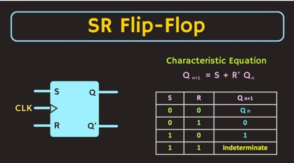
Image credit – all about electronics
The SR type, also known as the Set-Reset flip-flop, is an electronic circuit that can retain a single bit of information. It has two inputs: the Set (S) input and the Reset (R) input, and two outputs: the Q output and the Q̅ (not Q) output. When the Set input is HIGH (1), the Q output is established to HIGH (1). When the Reset input is HIGH (1), the Q output is set to LOW (0).
here’s the truth table for an SR (Set-Reset) flip-flop:
| S | R | Q (output) | Q̅ (complement) |
| 0 | 0 | Previous state | Previous state |
| 0 | 1 | 0 | 1 |
| 1 | 0 | 1 | 0 |
| 1 | 1 | Not allowed | Not allowed |
Note: The third and fourth rows indicate the unstable condition, where both S and R are HIGH at the same time. This state is forbidden in synchronous circuits, as it can lead to unpredictable results.
D flip-flop (data flip-flop)
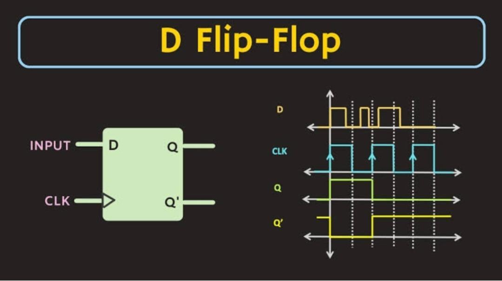
Image credit – all about electronics
The D flip-flop, also known as the data flip-flop, is an electronic circuit that can store a single bit of data. It features a solitary data input (D) and has two outputs: The Q output and the Q̅ (not Q) output. The output state of the D flip-flop only changes when there is a transition in the clock signal from LOW to HIGH. When the clock signal is HIGH, the value of the D input is transferred to the Q output. When the clock signal is LOW, the Q output maintains its previous state.
The truth table for the D flip-flop is as follows:
| Clk | D | Q (output) | Q̅ (complement) |
| 0 | X | Previous state | Previous state |
| 1 | 0 | 0 | 1 |
| 1 | 1 | 1 | 0 |
Here, X represents a “don’t care” state, which means that the output state is not dependent on the value of the input.
JK flip-flop
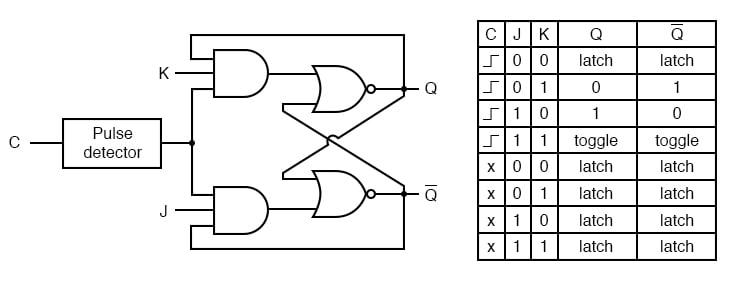
Image credit – all about circuits
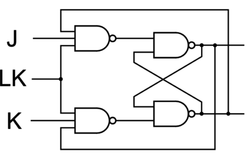
The JK flip-flop is an electronic circuit that stores a single bit of data. Unlike the SR flip-flop, the JK flip-flop does not have an unstable state. It features two inputs, J and K, and two outputs, Q and Q̅. The JK flip-flop’s output changes in response to both the clock signal and the J and K inputs. If J is HIGH and K is LOW, the output is set to HIGH when the clock signal is HIGH. Conversely, if K is HIGH and J is LOW, the output is set to LOW. If both J and K are HIGH, the output toggles between HIGH and LOW states with each clock pulse.
The truth table for the JK flip-flop is as follows:
| J | K | Clk | Q (output) | Q̅ (complement) |
| 0 | 0 | X | Previous state | Previous state |
| 0 | 1 | ↑ | 0 | 0 |
| 1 | 0 | ↑ | 1 | 0 |
| 1 | 1 | ↑ | Not allowed | Not allowed |
Here, X represents a “don’t care” state, which means that the output state is not dependent on the value of the input.
T flip flop
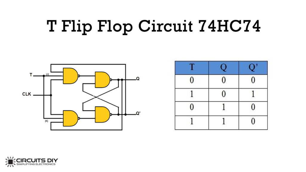
Image credit – circuits diy
The T flip-flop is a digital circuit that stores a single bit of data. It is an edge-triggered circuit that responds to a clock signal transition from LOW to HIGH. It has a single input, T, and two outputs, Q and Q̅. When the T input is HIGH. The output state changes to the opposite of its previous state when the clock signal transitions to HIGH. Conversely, when the T input is LOW, the output state remains the same.
The truth table for the T flip-flop is as follows:
| T | Clk | Q (output) | Q̅ (complement) |
| 0 | ↑ | Previous state | Previous state |
| 1 | ↑ | Complement of previous state | Inverse of previous state |
Here, the ↑ symbol represents the rising edge of the clock signal, which triggers the flip-flop’s output change.
Master-Slave flip-flop
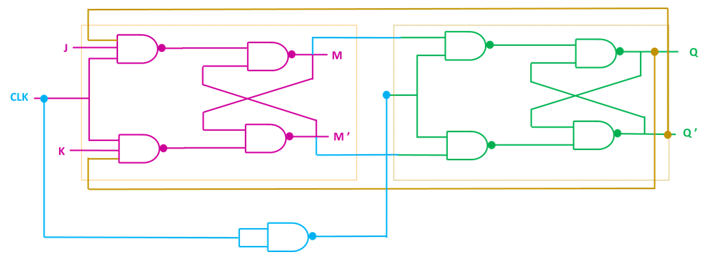
Image credit – all about electronics
The Master-Slave flip-flop is a type of digital circuit that is made up of two flip-flops: a master flip-flop and a slave flip-flop. This circuit is commonly utilized in digital systems for storing binary information.
It is clock-triggered, and its output feeds into the input of the slave flip-flop. The slave flip-flop is clocked by the inverse of the clock signal. Its output is saved in the slave flip-flop, and the slave flip-flop’s output is the final output of the circuit.
It has two outputs, Q and Q̅, and two inputs: a clock signal, CLK, and a data input signal, D. The truth table for the Master-Slave flip-flop is as follows:
| CLK | D | Q̅ (Slave) | Q (Master) | Q̅ (Master) | Q (Slave) |
| 0 | X | Q | Q̅ | Q | Q̅ |
| 1 | 0 | Q | Q̅ | Q | Q̅ |
| 1 | 1 | Q | Q̅ | Q | Q̅ |
Note that X denotes a “don’t care” state. The Master-Slave flip-flop is a level-sensitive circuit and is triggered by the rising or falling edge of the clock signal. In the first row of the truth table, the outputs Q and Q̅ are in the same state as the previous state when the clock is LOW. When the clock is HIGH, the inputs are stored in the master flip-flop. The slave flip-flop outputs the same value on Q and Q̅.
Edge-triggered flip-flop
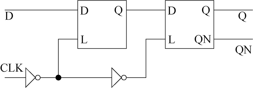
Image credit – Wikimedia commons
An edge-triggered flip-flop is a type of flip-flop that is activated by a signal transition. Instead of the level of the input signal. It is widely used in digital circuits to store and transfer binary data.
This type of flip-flop is activated by the rising or falling edge of the clock signal, depending on the flip-flop’s configuration. The output of the flip-flop changes only at the edge of the clock pulse and remains steady for the remainder of the cycle. This feature enables the edge-triggered flip-flop to be used in synchronous digital systems. Where several flip-flops are connected and triggered by the same clock signal.
There is no truth table for an edge-triggered flip-flop as it is a type of flip-flop. That is triggered by the edge of a clock signal rather than by the level of an input signal. However, the output of an edge-triggered flip-flop changes based on the input and the type of flip-flop being used.
For example, the truth table for a D-type edge-triggered flip-flop is as follows:
| Clock | D Input | Q (output) |
| 0 | X | Q(t) |
| 1 | 0 | 0 |
| 1 | 1 | 1 |
| 1 | X | Q(t) |
| 0 | X | Q(t) |
In this truth table, X represents a “don’t care” value, and Q(t) represents the current value of the output before the clock edge. When the clock transitions from 0 to 1, the output Q changes to the value of the D input. When the clock transitions from 1 to 0, the output Q remains at its current value.
Asynchronous flip flops

Image credit – all about circuits
An asynchronous, or ripple counter, is a type of digital circuit that utilizes flip-flops to count and store binary data. In an asynchronous counter, the flip-flops are connected in a cascaded manner. With the output of one flip-flop connected to the clock input of the next flip-flop. This setup allows the counter to count at a speed determined by the propagation delay of the flip-flops.
Asynchronous counters generally use D flip-flops, which have a data input, clock input, and an output. When the clock input of a D flip-flop transitions from 0 to 1 (rising edge). The output Q changes to the value of the data input D.
It does not have a single truth table, as it is a type of circuit that uses multiple flip-flops to count and store binary data. The count sequence and output of an asynchronous counter depend on the number of flip-flops used and the clock input.
Each flip-flop in an asynchronous counter has its own truth table, which is determined by the type of flip-flop used. In general, the output of a flip-flop changes in response to a clock signal and the state of the input(s).
Frequently asked questions
What is the working principle of flip-flops and what are they used for?
Flip-flops are fundamental components of digital circuits that can hold a single bit of binary data in two stable states. They are operated by a clock signal and have different types, each with specific functions and characteristics.
What are the different types of flip-flops, and how do they differ from each other?
Flip-flops can be classified into several types, such as SR flip-flop, D flip-flop, JK flip-flop, T flip-flop, and master-slave flip-flop. Each type has its own set of inputs and outputs. Their behavior depends on their design and internal circuitry.
What distinguishes synchronous and asynchronous flip-flops?
Synchronous flip-flops are triggered by a common clock signal. While asynchronous flip-flops respond to specific input signals. Synchronous flip-flops are used in applications that require precise timing and synchronization. While asynchronous flip-flops are used in simpler applications where timing is not critical.
What are the practical uses of flip-flops?
Flip-flops find application in various digital systems, such as counters, registers, and memory cells. They are also used in control circuits, communication systems, and computer processors.
What sets positive-edge-triggered flip-flops apart from negative-edge-triggered flip-flops?
Positive-edge triggered flip-flops change state at the rising edge of the clock signal. While negative-edge-triggered flip-flops change state at the falling edge of the clock signal. The choice of edge-triggering depends on the specific application and timing requirements.
Conclusion
To sum up, we’ve clearly explained” what is flip flop” . flip-flops are indispensable building blocks of digital circuits. That performs critical functions such as storing, synchronizing, and manipulating binary data. With diverse types of flip-flops at our disposal, each with its specific traits and uses. Comprehending their workings is vital to using them efficiently for different applications. Regardless of whether you’re a hobbyist, student, or expert, mastering the use of flip-flops is crucial to creating efficient digital circuits. That fuel today’s electronics and computing devices.