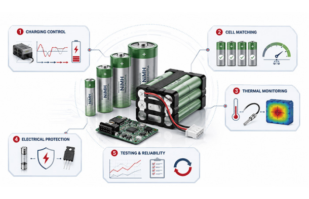

Choosing an industrial NiMH battery pack involves much more than matching voltage and capacity. You also need to understand how the cells, charger, operating temperature, protection components and equipment load work together throughout the battery’s service life.
Reliable performance is created at the system level—through coordinated cell selection, charging control, thermal design, electrical protection and repeatable manufacturing.
Industrial Reliability Is a System-Level Result
When you select a battery for industrial equipment, the voltage and rated capacity only describe part of the requirement. They do not tell you how the pack will behave during a peak load, after years of standby charging, inside a warm enclosure or when one cell begins aging faster than the others.
A battery pack may appear suitable on a specification sheet and still fail to deliver the runtime, stability or maintenance interval your equipment requires. To avoid that outcome, you need to evaluate the battery as part of the complete power system.
The Core Engineering Principle
Industrial NiMH engineering is not simply the process of connecting rechargeable cells.
It is the coordinated design of the cells, charger, thermal environment, electrical protection, mechanical structure, monitoring logic and manufacturing process. Every part of this system influences whether the battery pack remains safe, stable and predictable in real operation.
Small Battery Weaknesses Can Become Major Equipment Risks
You may not notice a battery-design problem during a short laboratory test. The consequences often appear later, when the pack is exposed to real temperatures, repeated charging, long standby periods and changing load conditions.
Unexpected Controller Shutdown
Excessive voltage drop can reset an industrial controller even when measured capacity appears sufficient.
Interrupted Medical or Test Equipment
Inconsistent charging or an aging weak cell can interrupt measurements, procedures or stored operating data.
Reduced Standby Readiness
Self-discharge differences can leave a backup pack unable to provide its expected runtime after a long idle period.
Shorter Maintenance Intervals
High enclosure temperatures and unsuitable maintenance charging can accelerate aging and increase replacement frequency.
Early Series-Pack Cutoff
One mismatched cell can reach its discharge limit before the rest of the series pack, reducing usable capacity.
What Industrial NiMH Battery Engineering Actually Covers
When you evaluate an industrial battery pack, you are not simply selecting several rechargeable cells and connecting them together. You are defining how the battery will interact with your equipment during charging, normal operation, peak loads, standby periods, environmental exposure and long-term aging.
A properly engineered NiMH Battery must therefore be evaluated as part of the complete device rather than as an isolated energy source. Its usable performance depends on the load profile, charging method, operating temperature, cutoff voltage, cell consistency and expected maintenance interval.
Industrial NiMH engineering connects your device requirements with cell selection, charging control, pack construction, thermal protection, diagnostics and repeatable manufacturing.
You can understand this engineering process through six closely connected layers. A weakness in any one layer can reduce runtime, shorten service life or make battery performance less predictable in the field.
Application Requirements
You first define what the equipment actually needs, including voltage range, runtime, continuous current, peak current, temperature, maintenance access and operating mode.
Cell and Pack Specification
You convert those requirements into cell size, cell count, capacity, series or parallel configuration, wire gauge, connector type and pack dimensions.
Charging and Termination
You determine the appropriate charging current, termination signals, temperature limits, maximum charge time and maintenance-charging strategy.
Thermal and Safety Architecture
You control heat, pressure, short-circuit risk and abnormal charging through sensors, fuses, PTC devices, insulation and suitable pack ventilation.
Monitoring and Diagnostics
You monitor capacity, runtime, temperature, voltage drop, internal resistance and self-discharge to understand the condition of the pack.
Testing and Manufacturing Control
You confirm that every production pack can repeatedly meet the intended electrical, thermal, mechanical and service-life requirements.
Translating Device Requirements into Battery Specifications
Before you select a cell format or calculate capacity, you need to understand how your equipment uses power. A battery pack that meets the nominal voltage on paper may still fail during startup, provide insufficient runtime or operate outside a suitable charging temperature range.
Your battery specification should therefore begin with the complete operating profile of the device. The following questions help you convert that profile into measurable pack requirements.
Electrical Requirements
● What nominal voltage does your device require?
● What are the highest and lowest acceptable operating voltages?
● What are the continuous and peak current demands?
● How long does each peak-current event last?
Runtime and Operating Mode
● How long must the equipment operate between charges?
● Is the load continuous, intermittent or mainly used for backup?
● Will the battery remain connected to a charger for long periods?
● How often can the equipment be serviced?
Mechanical Constraints
● How much installation space is available?
● Is there a maximum acceptable pack weight?
● Will the pack experience vibration, impact or movement?
● Does the application require a custom connector or mounting structure?
Environmental Conditions
● What temperatures will the battery experience during charging?
● What temperatures will apply during discharge and storage?
● Will humidity, dust or condensation affect the battery enclosure?
● Are there nearby motors, processors or power electronics generating heat?
Pack Voltage Requires More Than a Cell-Count Calculation
Dividing the device voltage by the approximately 1.2V nominal voltage of one NiMH cell may provide an initial cell-count estimate, but it does not complete the electrical design. Your device will experience a changing battery voltage throughout charging and discharge.
| Voltage Condition | What You Need to Verify |
| Fully charged pack voltage | Confirm that the device and charging circuit can tolerate the highest expected pack voltage. |
| Nominal operating voltage | Confirm that the normal operating range matches your system power architecture. |
| Voltage under load | Account for voltage drop caused by cell resistance, interconnects, wires and connectors. |
| End-of-discharge voltage | Confirm that the battery can still support the device before one cell becomes excessively discharged. |
| Device undervoltage cutoff | Determine how much rated capacity remains usable before the device shuts down. |
Rated Capacity Is Only the Starting Point
A capacity label describes performance under defined test conditions. Your actual runtime can be different because the battery inside your device is exposed to a different current profile, temperature, cutoff voltage and state of aging.
● Discharge current
● Operating temperature
● Cell age
● Pack resistance
● Cutoff voltage
● Previous charging conditions
Rated capacity is only the starting point. Available runtime also depends on discharge current, temperature, cell age, pack resistance, device cutoff voltage and previous charging conditions.
Do Not Ignore Short Peak Loads
Your equipment may draw only a modest average current and still place a demanding load on the battery. Motors, pumps, alarms, wireless transmitters, relays and startup circuits can create brief current peaks that are much higher than the steady operating load.
During these events, excessive voltage sag can reset the device or activate its undervoltage protection even when substantial capacity remains. You should therefore validate the complete pack—including cells, welds, wires and connectors—under the real peak-current waveform rather than relying only on an average current calculation.
NiMH Characteristics That Shape Pack Design
You do not need a long history of nickel-metal hydride chemistry to design an effective industrial battery system. What matters is understanding the characteristics that directly influence your pack voltage, charger, thermal design, runtime and maintenance strategy.
These characteristics explain why a NiMH pack must be evaluated under realistic load, temperature, charging and aging conditions.
Approximately 1.2V per Cell
The cell count establishes the pack’s nominal voltage, but your design must still accommodate the complete voltage range from charge completion to discharge cutoff.
Relatively Flat Discharge Profile
Voltage can remain comparatively stable through much of the discharge period, which supports predictable device operation but makes mid-range SOC estimation more difficult.
Load-Dependent Voltage
Higher current and increased internal resistance create greater voltage drop, especially in aged cells, cold conditions or high-resistance pack assemblies.
Temperature-Sensitive Performance
Temperature influences available capacity, charge acceptance, self-discharge, voltage response and long-term aging.
Weak-Cell Reversal Risk
In a deeply discharged series pack, a lower-capacity cell may reach empty first and be driven into reverse polarity while current continues through the string.
Charge-End Heat and Pressure
As the cell approaches full charge, charging efficiency falls and more input energy is converted into heat, making termination and temperature monitoring increasingly important.
Capacity Loss and Resistance Growth
Aging may reduce available capacity and increase internal resistance, causing shorter runtime, greater voltage sag and additional heat under load.
Why Voltage Alone Cannot Provide Reliable Mid-Range SOC
Because the NiMH discharge curve remains relatively flat over a large part of its usable capacity, two packs with different remaining charge may show similar resting voltages. The measured voltage can also change with load current, temperature, recovery time and cell condition.
For equipment that needs more accurate state-of-charge monitoring, you may need to combine current integration with temperature compensation, charge and discharge history, full-charge recognition and actual device runtime data. Voltage remains useful, but it should not be treated as the only source of SOC information.
Four Relationships You Need to Validate
Load Current: Higher current → greater voltage drop and heat
Temperature: Temperature change → different capacity and charging efficiency
Cell Aging: Aging → increased resistance and reduced runtime
Cutoff Voltage: Higher cutoff threshold → less usable capacity
Charging Architecture for Industrial NiMH Packs
When you design a charger for an industrial NiMH battery pack, you should not begin by choosing a single termination threshold. You first need to determine how quickly the battery must recharge, how long it may remain connected to the charger, what temperatures it will experience and how much charging stress the application can tolerate.
The correct charging architecture is a balance between recharge time, temperature rise, cycle-life expectations, standby readiness and the accuracy of the available voltage and temperature measurements. A method suitable for an occasionally charged instrument may not be appropriate for an emergency system that remains connected to mains power for years.
Standard Timed Charging
Standard charging generally uses a low constant-current rate for a controlled period. It can be suitable when recharge time is not critical and the battery is charged under predictable conditions.
You still need to account for the battery’s initial state of charge, rated capacity, charging efficiency, temperature and what happens if power is interrupted and the timer restarts.
Accelerated Charging
Accelerated charging uses a moderate charging current to shorten downtime without reaching the most aggressive fast-charge rates.
As charge current increases, you need tighter control over charging time, ambient temperature and battery temperature. The charger should also handle partially charged packs without repeatedly adding unnecessary overcharge.
Fast Charging
Fast charging applies a higher controlled constant current and requires reliable detection of charge completion. Near full charge, a larger portion of the input energy may become heat.
A maximum timer should remain available as a backup, but it should not be the only termination method. Voltage behavior, temperature rise and abnormal sensor conditions also need to be monitored.
Maintenance and Standby Charging
Standby systems require a different strategy from portable equipment. You may need to maintain readiness without exposing the cells to continuous excessive overcharge.
The permissible maintenance current depends on the cell family, ambient temperature, standby duration and required recovery time after a mains-power interruption.
Standard Timed Charging Requires More Than a Timer
A low-rate timed charger may appear simple, but its reliability still depends on how the timer is initialized and how the charger responds to a battery that is already partially charged. If a power interruption resets the timing sequence, the pack may receive another complete charging period even though it has already absorbed much of the required energy.
For this reason, you should evaluate timer restart behavior, initial SOC, charging efficiency and maximum battery temperature. A timer can define the normal charging window, but temperature supervision and a safe current level are still required.
Faster Charging Increases the Need for Accurate Control
As you increase the charge rate, charge completion must be detected more accurately. A fast charger that terminates too early reduces available runtime, while a charger that terminates too late increases temperature, internal pressure and long-term stress.
Faster charging can improve equipment availability, but it also makes voltage measurement, temperature sensing, fault detection and termination logic more important.
Maintenance Charging Is Not One Universal Current
You should distinguish between several different standby strategies. A continuous trickle charge applies a low current continuously. An intermittent maintenance charge applies charging current only at selected intervals. A backup system may also require a rapid recharge after mains failure, followed by a lower maintenance stage.
Trickle Charge
A low continuous current intended to compensate for self-discharge.
Intermittent Maintenance
Periodic charging used to maintain readiness while reducing continuous overcharge exposure.
Post-Outage Recharge
A controlled recharge stage following a real backup-power event.
Standby Compensation
A long-term strategy adjusted for self-discharge, ambient temperature and required availability.
Manufacturer examples show that some NiMH cell families may use maintenance currents around 0.01C to 0.03C, while certain standby designs use approximately 0.03C. These values should be treated as product-specific references rather than universal limits. Your final current should follow the selected cell specification and the validated thermal conditions inside the equipment.
Multi-Signal Charge Termination and Fault Handling
No single charging signal remains equally clear under every operating condition. Battery temperature, charge rate, cell age, initial SOC, measurement noise and pack consistency can all change the way charge completion appears.
For an industrial charger, you should combine a primary termination method with independent backup protections. The purpose is not to find one perfect signal. It is to ensure that a weak or missing signal does not allow the pack to continue charging without control.
Negative Delta V
During higher-rate charging, the cell voltage typically rises toward a peak and may then show a small decline as full charge is reached. A charger can monitor this negative voltage change as one indication that charging should end.
● The signal depends on the cell design and charging rate.
● High battery temperature can make the voltage behavior less distinct.
● Low charge rates and mismatched cells can weaken or distort the pack-level signal.
Manufacturer references may show examples ranging from approximately 5mV to 20mV per cell. These are product-specific values, not one universal NiMH threshold.
Temperature-Rate Detection
As a NiMH cell approaches full charge, its ability to store additional energy decreases and the rate of temperature rise may increase. A charger can monitor dT/dt to detect this change.
● The sensor must remain in reliable thermal contact with the pack.
● The enclosure and nearby heat sources can influence the measured temperature.
● The correct rate threshold must be validated for the selected cell and pack structure.
A reference such as 0.7°C per minute may apply to a particular high-rate product series, but it should not be treated as a universal value for every industrial NiMH pack.
Backup Protections Should Remain Independent
Primary termination signals can become unclear when the battery is hot, partly charged, aged or poorly matched. Your charger should therefore include several independent limits that stop or restrict charging when normal behavior is not detected.
Absolute Temperature Cutoff
Stops charging when the battery reaches the project-defined maximum temperature.
Maximum Charge Timer
Prevents indefinite charging when normal termination is not detected.
Maximum Pack Voltage
Detects an abnormal voltage rise or an incompatible battery condition.
Low-Voltage Detection
Identifies a deeply discharged, damaged or incorrectly connected pack before fast charging begins.
Sensor Fault Detection
Prevents charging when a thermistor is open, shorted or outside a realistic range.
Charger Restart Lockout
Prevents repeated charge cycles caused by brief power interruptions or unstable supply conditions.
Pre-Charge or Recovery Handling
Uses a reduced current or qualification stage before normal charging of a deeply discharged pack.
A robust industrial charger uses layered termination and fault handling rather than relying on one perfect signal.
How the Charger Should Progress
Temperature Qualification → Constant-Current Charging → Voltage and Temperature Sampling → −ΔV or dT/dt Detection → Maximum-Time Backup → Charge Stop or Maintenance Mode
Cell Matching: Why the Weakest Cell Limits the Pack
A series-connected battery pack may contain cells with the same model number and rated capacity, but that does not mean they will behave identically. Small differences in capacity, resistance, self-discharge and aging can become more significant after repeated cycling and long standby periods.
The usable performance of your pack is often limited by the cell that reaches its voltage, temperature or capacity limit first. For that reason, cell matching is not only a manufacturing-quality activity. It is part of the electrical and thermal design of the complete battery pack.
Capacity Matching
A lower-capacity cell reaches the end of discharge before the other cells in the series string. If the equipment continues drawing current, the weak cell may be driven into excessive discharge or reverse polarity.
You should define the permitted capacity window according to the number of series cells, expected depth of discharge, load profile and service-life target rather than applying one fixed percentage to every project.
DC Internal Resistance Matching
In a series pack, the same current flows through every cell. Resistance differences therefore do not create unequal current sharing between the series-connected cells.
They create different voltage drops and different levels of heat. A higher-resistance cell may reach the device cutoff voltage earlier and operate at a higher temperature under the same load.
Self-Discharge Matching
In a standby system, the pack may remain unused for weeks or months. A cell with a higher self-discharge rate can lose SOC faster than the rest of the string.
When the backup event finally occurs, that cell may limit runtime even though the pack initially passed a capacity test. Self-discharge screening is therefore important for long-idle applications.
Temperature and Aging Consistency
Cells with different manufacturing histories or storage conditions may age at different rates even when their initial capacity appears similar.
You should consider production lot, formation history, storage temperature, transportation conditions, present SOC, DCIR and measured heat generation during qualification.
In a series pack, identical current does not mean identical cell behavior. Capacity and resistance differences still create unequal voltage, temperature and depth-of-discharge conditions.
Parallel Structures Require Additional Current-Sharing Control
When cells or strings are connected in parallel, resistance consistency directly affects current distribution. A lower-resistance path may carry a larger share of the load or charging current. For parallel designs, you should evaluate interconnect resistance, conductor symmetry, thermal coupling and the electrical behavior of each parallel path.
Recommended Cell-Sorting Parameters
Your sorting process should focus on the parameters that affect real pack performance. The final limits should reflect the application rather than a generic industry percentage.
| Matching Parameter | Engineering Purpose |
| Capacity | Reduces early discharge limitation and helps the cells reach the discharge endpoint more consistently. |
| DC Internal Resistance | Limits unequal voltage drop and heat generation under the same series current. |
| Self-Discharge | Maintains more consistent SOC during storage and long standby periods. |
| Open-Circuit Voltage | Helps identify abnormal cells, incorrect SOC or unusual self-discharge before assembly. |
| Temperature Response | Identifies cells that generate unusual heat during charging or high-load operation. |
| Lot and Age | Improves consistency of formation history, material condition and long-term aging behavior. |
The Same Current Can Produce Very Different Cell Conditions
Matched Pack
● Similar voltage drop under load
● More uniform temperature rise
● More consistent discharge endpoint
● Better use of the available pack capacity
Mismatched Pack
● One cell reaches low voltage earlier
● Higher-resistance cells generate more heat
● Pack-level charge signals become less clear
● Usable runtime is limited by the weakest cell
Thermal Design for NiMH Battery Packs
When you design an industrial NiMH battery pack, thermal management does not usually begin with liquid cooling, HVAC equipment or phase-change materials. For most embedded, backup and portable industrial systems, the first task is to understand where heat is generated, how it moves through the pack and whether it can escape from the equipment enclosure.
Your objective is to prevent sustained overtemperature, detect abnormal charging behavior and avoid local hot spots that accelerate aging. Even when the average enclosure temperature appears acceptable, one cell, weld, wire or connector may operate at a significantly higher temperature than the rest of the pack.
Effective NiMH thermal design is usually achieved through suitable cell spacing, controlled airflow, a clear heat path, correct sensor placement and validation inside the actual device enclosure.
Start by Mapping Every Important Heat Source
The cells are not the only components that influence battery temperature. You should evaluate the complete device because heat from processors, motors, transformers, power converters and charging circuits may flow into the battery compartment even when the pack itself is not under a heavy load.
Cell Spacing
Closely packed cells can retain heat and influence each other. Suitable spacing can improve airflow, reduce thermal coupling and make abnormal hot cells easier to detect.
Airflow
Natural or forced airflow should pass through the battery area rather than around it. Internal partitions, cables and nearby components can block the intended air path.
Enclosure Heat Path
Heat must have a realistic path from the cells to the surrounding air or enclosure wall. Thick insulation and sealed cavities may slow heat release.
Nearby Device Heat
Motors, processors, relays, transformers and power electronics can raise battery temperature before charging or discharge even begins.
Wires and Welds
Undersized wires, weak welds and high-resistance connectors can generate local heat that may be mistaken for normal cell heating.
Charger Location
If the charger and battery pack operate in different thermal environments, charger-board temperature may not represent the actual cell temperature.
Closed-Cavity Accumulation
Repeated charging inside a sealed compartment can cause heat to accumulate from one cycle to the next, especially when cooling time is limited.
Design the Thermistor Around the Real Hot Spot
Adding a thermistor does not automatically provide effective temperature protection. The sensor only protects the pack when it accurately represents the cells most likely to become hot during charging or heavy discharge.
You should determine the sensor location through thermal testing inside the final enclosure. A sensor mounted on an easily accessible but cooler outer surface may respond too slowly, while a sensor exposed to direct airflow may report a temperature lower than the internal cell group.
Measure the Hottest Expected Area
Position the sensor close to the cell or cell group expected to experience the greatest temperature rise.
Maintain Reliable Thermal Contact
The thermistor should remain securely coupled to the pack during vibration, handling and long-term service.
Avoid Misleading Cooling Effects
Do not place the sensor where external airflow, a metal bracket or enclosure wall makes it appear cooler than the cells.
Charging Temperature and Discharge Temperature Are Not the Same Limit
You should not describe every industrial NiMH battery as having one universal operating range such as 0°C to 45°C. The acceptable temperature window depends on the specific cell family, charging rate, discharge rate, maintenance strategy and required service life.
Charging is often subject to tighter limits than discharge because charge acceptance and temperature rise change significantly at temperature extremes. Fast charging may therefore require a narrower qualification window than low-rate timed charging.
| Example Charging Mode | Example Product-Specific Range | How You Should Interpret It |
| Standard charging | 0°C to 65°C | An example from one specific high-rate product series, not a universal NiMH limit. |
| Accelerated or fast charging | 10°C to 45°C | Faster charging may require a narrower temperature qualification window. |
| Trickle charging | 10°C to 35°C | Continuous maintenance exposure may justify a different range from normal charging. |
These ranges should only be used as an example of how one manufacturer differentiates charging modes. Your final thermal limits must come from the selected cell specification and validation under the actual pack and equipment conditions.
Multi-Layer Safety Architecture
NiMH safety engineering should not be reduced to a statement that the chemistry is safe or that one protection component will prevent every failure. You need a coordinated architecture that manages overcharge heat, gas pressure, venting, leakage, short circuits, cell reversal and abnormal temperature.
The most reliable design does not depend on a single fuse, sensor or charger algorithm. It uses several layers so that one abnormal condition can be detected or limited before it becomes a device-level failure.
A complete industrial NiMH safety strategy connects the cell, battery pack, charger and host device. Each layer addresses different failure conditions and supports the layers around it.
Cell Level
Cell-level safety begins with the internal construction and consistency of the selected cell. Reliable sealing, suitable electrode and separator materials, controlled manufacturing and the intended pressure-management design all influence how the cell responds to normal and abusive conditions.
● Reliable sealing
● Pressure relief design
● Qualified electrodes
● Separator integrity
● Manufacturing consistency
Pack Level
Pack-level protection addresses faults that arise after cells are connected with welds, wires, insulation and connectors. The selected components should match the maximum current, expected fault energy, temperature environment and service requirements.
● Fuse
● Thermal fuse
● PTC device
● Thermistor
● Insulation barriers
● Polarity protection
● Strain relief
● Mechanical retention
Charger Level
Charger-level protection controls how energy enters the battery. The charger should qualify the pack before charging, regulate current, identify charge completion and respond safely to missing or contradictory voltage and temperature signals.
● Current regulation
● Charge termination
● Maximum timer
● Temperature qualification
● Abnormal-cell detection
● Restart management
Device Level
The host device provides the final layer by controlling how the battery is used and how the equipment responds to low voltage, excessive current or an aging pack. A controlled shutdown is usually safer than allowing unstable operation to continue.
● Undervoltage cutoff
● Short-circuit protection
● Overload control
● Fault logging
● Replacement notification
● Safe shutdown
Pressure Relief Is a Cell-Specific Safety Feature
Some NiMH cells include an internal pressure-relief or resealable vent mechanism. This can help the cell respond to excessive internal gas pressure, but the design, opening behavior and resealing capability are specific to the individual cell construction.
You should therefore avoid applying one generic pressure value to all industrial NiMH cells. The correct information must come from the selected manufacturer’s product specification and qualification documentation.
Does an Industrial NiMH Pack Need a BMS?
The answer depends on what you mean by battery management. A small NiMH pack may not require the same cell-level protection and balancing architecture commonly associated with a multi-cell lithium-ion pack. It may still require a dedicated charger, temperature sensor, fuse and equipment-level undervoltage control.
A larger or higher-risk system may add a fuel gauge, pack-protection circuit, current monitor, supervisory controller or communication interface. The architecture should reflect the pack size, charging rate, device risk, maintenance needs and required diagnostic accuracy.
Charge Controller
Regulates charging current and evaluates voltage, temperature and time.
Protection Circuit
Provides current, temperature or fault protection appropriate to the pack.
Fuel Gauge
Estimates remaining charge, runtime or battery condition when the application requires it.
Supervisory Controller
Coordinates charging, diagnostics, fault logging and communication with the host equipment.
Engineering Principle: NiMH packs may use a dedicated charge controller, pack-protection circuit, fuel gauge or supervisory controller. The required architecture depends on pack size, charge rate, application risk and diagnostic requirements.
SOC, SOH, and Practical Diagnostics
When your equipment depends on a NiMH battery pack, you usually need to answer two different questions. The first is how much usable charge remains now. The second is whether the battery can still deliver the runtime, voltage stability and peak-current performance your device requires.
These questions correspond to state of charge and state of health. They should not be treated as the same measurement. A battery may be fully charged and still be unable to support a demanding load because its capacity has declined or its internal resistance has increased.
How Much Usable Charge Remains?
SOC estimates the battery’s present charge level. You use it to predict remaining runtime, schedule recharging and decide whether the equipment can complete its next operating cycle.
Can the Battery Still Meet the Device Requirement?
SOH describes how the pack’s capacity, resistance, self-discharge, thermal behavior and load capability have changed compared with its qualified condition.
Estimating State of Charge in a NiMH System
NiMH voltage remains relatively flat through much of the discharge period. This means a single voltage reading may help you recognize a nearly full or nearly empty battery, but it is usually not sufficient for accurate estimation across the complete SOC range.
For more reliable NiMH battery SOC estimation, you should combine several inputs and update the estimate as the pack is charged, discharged, stored and exposed to changing temperatures.
Coulomb Counting
Current is measured and integrated over time so you can estimate how much charge enters or leaves the battery.
Charge-Efficiency Compensation
Not every ampere-hour supplied by the charger becomes stored capacity, especially near full charge and at unfavorable temperatures.
Self-Discharge Compensation
The estimate should account for charge lost while the equipment is stored, idle or disconnected from the charger.
Temperature Correction
Available capacity, charge acceptance and self-discharge change with temperature, so one fixed model may not remain accurate.
Full and Empty Recalibration
Recognized full-charge and end-of-discharge events can be used to correct accumulated estimation error.
Actual-Load Runtime Estimation
Remaining runtime should reflect the device’s real current profile, cutoff voltage and expected peak loads.
NiMH voltage is useful as one diagnostic input, but accurate SOC estimation usually requires current history, temperature information, efficiency compensation and periodic recalibration.
State of Health Should Reflect Real Device Performance
A useful SOH model should tell you whether the battery remains capable of supporting the equipment, not only whether its laboratory capacity has declined. In many industrial applications, increased resistance or excessive self-discharge becomes operationally important before capacity reaches a generic replacement threshold.
You should prioritize measurements that directly reveal changes in runtime, voltage stability, thermal behavior and standby readiness.
| Diagnostic Indicator | What It Can Reveal |
| Measured capacity | Shows how much charge the pack can deliver under a defined discharge test. |
| DC internal resistance | Indicates how much voltage drop and heat may be produced under load. |
| Voltage sag under pulse load | Reveals whether the pack can support startup, motor, relay or communication peaks. |
| Charge temperature rise | Helps identify reduced charge efficiency, rising resistance or abnormal cells. |
| Self-discharge | Shows whether the pack can remain ready during storage or extended standby. |
| Recharge time | May indicate changing capacity, charge acceptance or termination behavior. |
| Runtime to device cutoff | Provides direct evidence of whether the battery still meets the equipment requirement. |
| Cell-to-cell voltage spread | Identifies increasing imbalance or a cell approaching an abnormal condition. |
| Cycle count and depth | Provides operating-history context but should not be used alone to predict remaining life. |
Where Electrochemical Impedance Spectroscopy Fits
Electrochemical impedance spectroscopy may be used as an advanced laboratory or research diagnostic method. It can help engineers study electrochemical changes across a range of frequencies and compare aging behavior under controlled conditions.
However, EIS should not be presented as a standard feature that every industrial NiMH pack performs periodically. For most field systems, capacity, DC resistance, pulse-load response, temperature rise, self-discharge and real runtime provide more practical diagnostic information.
Define End of Life Around the Equipment Requirement
A battery should not automatically be declared suitable simply because it retains a selected percentage of its initial capacity. Capacity retention can be one criterion, but the actual replacement decision should reflect whether the pack still performs safely and predictably inside the device.
Insufficient Device Runtime
The pack can no longer meet the minimum operating time required by the equipment.
Excessive Voltage Sag
Startup or pulse loads cause the device to reset or reach its undervoltage cutoff.
Excessive Charge Temperature
Battery temperature exceeds the project limit or rises more rapidly than expected.
Faster Self-Discharge
Standby readiness declines before the next scheduled maintenance or test.
Growing Cell Imbalance
Cell voltage, resistance or temperature differences become too large for reliable operation.
Unacceptable Maintenance Frequency
The pack requires testing, recharging or replacement more often than the application allows.
Diagnostic Principle: The most useful battery-health metric is the one that tells you whether the pack can still support the real electrical, thermal and runtime demands of your equipment.
NiMH Battery vs Lithium-Ion for Industrial Equipment
Comparing NiMH and lithium-ion batteries only by energy density can lead you to the wrong engineering decision. The battery has to work with the device’s voltage range, charger, enclosure, load profile, maintenance plan and safety architecture.
A practical nimh battery vs lithium ion evaluation should consider the complete system rather than comparing energy density alone. Charging architecture, available enclosure space, peak-current demand, standby behavior, temperature, maintenance access, protection complexity and compatibility with existing equipment can all influence the final decision.
The correct question is not which chemistry is universally better. It is which chemistry produces the most reliable complete system for your application.
| Engineering Factor | NiMH | Lithium-Ion |
| Nominal cell voltage | Approximately 1.2V per cell. | Commonly around 3.6V to 3.7V, depending on chemistry. |
| Energy density | Lower, requiring more space and weight for equivalent stored energy. | Higher, supporting smaller and lighter product designs. |
| Charge control | Commonly uses controlled current with voltage, temperature and time-based termination. | Commonly uses CC/CV charging with dedicated electrical protection. |
| Voltage profile | Relatively flat through much of the discharge period. | Depends on the selected lithium-ion chemistry and load conditions. |
| Self-discharge | Generally higher and important to evaluate in standby applications. | Generally lower, supporting longer charge retention during storage. |
| Pack management | Can be comparatively simple in some applications but still requires correct charging and protection. | Commonly requires cell protection, monitoring and controlled charging. |
| Existing-equipment compatibility | Often compatible with equipment already designed around nickel-based 1.2V cells. | May require charger, voltage, protection or enclosure redesign. |
| Size and weight | Larger and heavier for the same energy requirement. | More compact when energy density is a primary design constraint. |
| Maintenance strategy | Suitable for many serviceable systems with established replacement and charging procedures. | Suitable where higher energy density and lower self-discharge justify additional management complexity. |
NiMH May Fit Better When
● Your existing device is designed around a 1.2V-cell architecture.
● You can accept more pack volume in exchange for a mature system design.
● The product has an established NiMH charging and maintenance strategy.
● The battery is intended for industrial controls, instruments, backup systems or serviceable equipment.
● Compatibility and predictable maintenance matter more than minimum weight.
Lithium-Ion May Fit Better When
● Your product has strict size and weight limits.
● Longer runtime is required from a compact battery volume.
● The system can support a dedicated protection and monitoring architecture.
● Lower self-discharge is important during long storage periods.
● The product can be redesigned around lithium-ion voltage and charging requirements.
Include Lifecycle Cost in the Decision
Battery cost should include more than the price of the cells. You may also need to consider charger redesign, protection electronics, certification work, enclosure changes, replacement labor, downtime, transportation and the cost of maintaining compatibility with existing equipment.
A chemistry with a higher initial energy density may not produce the lowest lifecycle cost when it requires extensive product changes. In the same way, retaining an established NiMH design may not be economical when size, weight or storage requirements have changed significantly.
Selection Principle: The better chemistry is the one that satisfies your device’s electrical, thermal, mechanical, maintenance and safety requirements with an acceptable lifecycle cost.
Electrical and Mechanical Pack Design
Once you have selected the cells, the reliability of your battery pack still depends on how those cells are connected, protected, supported and integrated into the equipment. A pack can contain qualified NiMH cells and still fail because of excessive connection resistance, inadequate wire sizing, weak welds or poor mechanical restraint.
You should therefore treat the battery pack as a complete electrical and mechanical assembly. Every interconnect, wire, connector, sensor, fuse and structural component influences voltage delivery, temperature, serviceability and long-term field performance.
Pack reliability can be limited by an undersized wire, weak weld, high-resistance connector, poorly positioned thermistor or inadequate mechanical support even when the cells themselves meet specification.
Delivering Stable Power to Your Device
Your electrical design must support the required pack voltage and current without creating excessive voltage drop, localized heating or unreliable protection behavior.
Series and Parallel Configuration
Define the cell arrangement around voltage, capacity, current demand and the risks introduced by parallel paths.
Interconnect Resistance
Include cell tabs, welds, bus strips, wires and connectors in the complete resistance budget.
Nickel Strip Dimensions
Select strip thickness and width for the expected continuous current, peak current and allowable temperature rise.
Wire Gauge
Use wire capable of carrying the real load without excessive loss, heating or mechanical fatigue.
Connector Current Rating
Confirm current capability under repeated connection, vibration, temperature and long-term contact aging.
Fuse Position
Position the fuse so it protects the maximum practical portion of the pack wiring and output path.
Thermistor Circuit
Verify sensor type, resistance curve, wiring, connector pins and charger interpretation.
Polarity and Pin Assignment
Make power, sensor and communication pins difficult to reverse, misalign or incorrectly mate.
Contact Resistance
Include aging, contamination and repeated mating when evaluating connector performance.
Voltage-Drop Budget
Define how much voltage can be lost across cells, welds, wires and connectors before the device reaches cutoff.
Protecting the Pack Throughout Service
Your mechanical design should prevent movement, abrasion, connector loosening and insulation damage while still allowing the pack to be manufactured, installed and serviced consistently.
Cell Retention
Prevent cells from shifting, rotating or placing repeated stress on welds and wires.
Vibration Resistance
Support the pack and wiring so repeated vibration does not weaken connections or insulation.
Shock Protection
Limit cell movement and impact forces during drops, handling or equipment transport.
Electrical Insulation
Protect exposed tabs, cell terminals, interconnects and conductive enclosure surfaces.
Heat-Shrink or Enclosure
Choose packaging that protects the pack without trapping excessive heat or damaging the cells.
Cable Strain Relief
Prevent pulling or bending forces from reaching internal solder joints, welds or sensor leads.
Connector Locking
Use a secure mating method when vibration or accidental disconnection could interrupt operation.
Service and Replacement Access
Design replacement procedures that reduce incorrect installation, wiring damage and excessive downtime.
Expansion and Tolerance
Allow for component tolerances, assembly variation, thermal movement and long-term material compression.
Build a Complete Voltage-Drop Budget
When your device has a defined undervoltage cutoff, the battery cells are not the only source of voltage loss. Every electrical connection between the cell and the device input consumes part of the available voltage margin.
Cell Resistance + Weld Resistance + Strip and Wire Resistance + Connector Resistance = Total Pack Voltage Drop
You should calculate and measure this voltage drop at the maximum expected load, then repeat the test after thermal cycling, vibration and aging. A connection that performs well when new may become the dominant limitation after extended service.
Testing and Validation Under Real Application Conditions
A battery pack should not be approved only because its cells meet a datasheet specification or because one laboratory discharge test was successful. Your equipment exposes the pack to a unique combination of charging behavior, load pulses, enclosure temperature, vibration, storage periods and cutoff conditions.
A reliable validation plan moves through several levels, beginning with cell qualification and ending with complete device-level testing. Each level answers a different question and reduces the risk of discovering a system incompatibility after production begins.
Passing a cell test does not prove pack performance, and passing a pack test does not prove that the battery will operate correctly inside your final equipment.
Cell Qualification
Confirm that the selected cells can provide consistent electrical and thermal behavior before they are assembled into packs.
● Capacity
● Open-circuit voltage
● DC internal resistance
● Self-discharge
● Temperature behavior
● Lot consistency
Pack Electrical Testing
Verify that the assembled pack delivers the expected voltage, current, protection and sensor behavior.
● Nominal voltage
● Maximum voltage
● Pack capacity
● Continuous discharge
● Peak-load response
● Voltage drop
● Short-circuit protection
● Charge termination
● Sensor response
Environmental Testing
Confirm that the electrical and mechanical design remains stable across the environment expected during transport, storage and operation.
● High temperature
● Low temperature
● Temperature cycling
● Vibration
● Mechanical shock
● Humidity where applicable
● Storage recovery
Life Testing
Reproduce the charging, standby and discharge conditions that will shape battery aging in the real application.
● Cycle life under intended charging
● Calendar aging
● Standby maintenance charging
● Mains-failure simulation
● Capacity trend
● Resistance trend
Device-Level Validation
This is the most important validation stage because it confirms whether the battery, charger, enclosure and host equipment operate correctly as one system.
● Charge inside the real device: Verify charger behavior and thermal conditions in the final installation.
● Measure temperature in the final enclosure: Confirm hot spots, thermistor response and cooling time.
● Use the real load profile: Include startup, motors, relays, communication pulses and idle periods.
● Test runtime to device cutoff: Use the actual undervoltage threshold instead of a generic cell endpoint.
● Simulate an aged pack: Check whether increased resistance and reduced capacity affect startup or runtime.
● Test sensor faults: Confirm safe behavior when a thermistor is open, shorted or disconnected.
● Test power restoration: Verify charger restart logic after brief and extended mains interruptions.
● Confirm safe shutdown: Ensure the device preserves data and enters a controlled state before power becomes unstable.
Apply Standards According to the Actual Product
IEC 61951-2 addresses marking, dimensions, testing and related requirements for certain portable sealed NiMH cells, including small cylindrical, prismatic and button-cell formats. It can provide an important reference for qualifying applicable products.
The complete standards and certification plan should still be selected according to your battery construction, host equipment, target market, transportation method and application category. One cell standard should not be treated as the complete compliance framework for every industrial battery pack.
Manufacturing Consistency and Traceability
A validated design only becomes a reliable industrial product when the manufacturing process can reproduce it consistently. Cell selection, welding energy, component placement, connector polarity and final testing must remain controlled from one production batch to the next.
You need more than a final pass-or-fail test. A strong production process controls the important inputs, records critical results and allows you to trace a finished battery pack back to its cells, components, assembly conditions and inspection history.
Manufacturing quality is the process of repeatedly turning an approved battery design into packs with consistent electrical, thermal, mechanical and diagnostic behavior.
Control the Process from Incoming Cells to Final Inspection
Incoming Cell Inspection
Verify cell model, production lot, appearance, voltage, resistance and required incoming quality criteria.
Cell Grading and Matching
Group cells according to the capacity, resistance, voltage and self-discharge limits defined for the project.
Welding Parameter Control
Control welding energy, pressure, electrode condition and placement to produce repeatable low-resistance connections.
Weld-Strength Verification
Confirm that welds withstand the mechanical forces expected during assembly, transport, vibration and service.
Connector Polarity Inspection
Verify power, thermistor and communication pins before the pack reaches final testing or the customer’s equipment.
Thermistor Verification
Confirm the correct sensor type, resistance, position, attachment and electrical connection.
Protection-Component Inspection
Check fuse, thermal fuse, PTC and insulation components against the approved bill of materials and assembly drawing.
Pack Capacity Testing
Confirm that the finished pack delivers the required capacity under the defined test current and cutoff voltage.
Aging and Self-Discharge Sampling
Use controlled sampling to identify abnormal charge retention, early failure or production drift.
Serial or Batch Traceability
Link finished packs to production lots, cells, materials, process records and inspection results.
Application-Specific Inspection
Confirm dimensions, labels, wire length, connector fit, output polarity and customer-specific electrical requirements.
Manufacturing Support Should Connect Design and Production
Your manufacturing partner should understand why each specification exists. Connector selection, wire length, fuse placement and thermistor position are not cosmetic customizations. They affect voltage delivery, thermal protection, installation reliability and compatibility with the host device.
Manufacturers such as GMCELL can support industrial NiMH projects by coordinating cell selection, pack configuration, connector and wire customization, temperature-sensing components, electrical protection, production testing and application-specific documentation.
Before Production
Confirm the pack drawing, electrical specification, component list, cell-matching limits and inspection plan.
During Production
Control welding, polarity, sensor installation, protection components and critical dimensional requirements.
Before Shipment
Verify output voltage, capacity, insulation, connector fit, labeling and project-specific documentation.
Traceability Helps You Investigate and Improve
When a field issue occurs, traceability allows you to determine whether the affected packs share a cell lot, welding station, connector batch, production date or test result. Without this information, investigation becomes slower and corrective action may affect more products than necessary.
Traceability also supports continuous improvement. Capacity, resistance, weld quality, self-discharge and field-return data can reveal trends before they become widespread reliability problems.
Manufacturing Principle: A reliable industrial NiMH pack requires both a validated engineering design and a controlled manufacturing process that can reproduce the design consistently throughout production.
Common Failure Modes and Troubleshooting Logic
When an industrial NiMH battery pack does not perform as expected, replacing the cells immediately may not solve the real problem. The fault may originate from the charger, temperature sensor, connector, welds, device cutoff setting or operating environment.
A more effective troubleshooting process begins with the observed symptom and then separates possible causes across the cell, pack, charger and host-device levels. This prevents you from treating every runtime or temperature problem as a cell-capacity failure.
A useful diagnosis compares voltage, current, temperature and runtime under the exact condition that produces the failure.
| Observed Symptom | Possible Engineering Causes |
| Pack becomes hot before full charge | Incorrect charging current, delayed or weak termination, poor thermistor contact, misleading sensor placement, high ambient temperature, aged cells or excessive connection resistance. |
| Runtime is much shorter than expected | Device cutoff voltage is too high, usable capacity was estimated under different conditions, cells are mismatched, internal resistance has increased, the pack is cold or previous charging was incomplete. |
| Pack works at light load but fails at startup | Excessive voltage sag, high cell DCIR, undersized wires, high connector resistance, weak welds or a startup current that was not included in the original design. |
| One cell repeatedly reaches low voltage first | Capacity mismatch, higher self-discharge, increased internal resistance, cell damage, different aging history or uneven pack temperature. |
| Standby pack loses readiness | Excessive self-discharge, inadequate maintenance charging, high enclosure temperature, long service interval, charger interruption or one cell losing SOC faster than the rest. |
| Charge termination is inconsistent | Changing battery temperature, noisy voltage measurement, weak −ΔV response, incorrect sampling logic, poor thermistor placement, partially charged cells or a mismatched series pack. |
| Pack life is shorter than the laboratory result | Deeper discharge, faster charging, higher operating temperature, continuous maintenance overcharge, real load pulses, limited cooling time or different device cutoff conditions. |
Use the Failure Condition as Your Test Condition
If the pack fails only during startup, testing it under a low constant-current discharge will not reproduce the problem. If the pack overheats only after several recharge cycles inside a sealed enclosure, an open-air bench test may hide the real thermal condition.
You should reproduce the same load pulse, enclosure, ambient temperature, charging history, battery age and device cutoff behavior that were present when the fault occurred.
Measure at the Cell and Pack
Compare individual cell voltage, total pack voltage and voltage at the device input to identify where loss occurs.
Record Temperature Over Time
Track cell, connector and enclosure temperatures rather than relying on one measurement after the test.
Check Charging History
Confirm whether the pack was fully charged, repeatedly restarted or exposed to prolonged maintenance charging.
Compare New and Aged Packs
The difference can reveal whether the design has sufficient voltage, thermal and capacity margin at end of life.
Troubleshooting Principle: Do not ask only whether the cells are good or bad. Ask which part of the complete battery system prevents your equipment from meeting its required performance.
Engineering Checklist Before Finalizing a NiMH Pack
Before you approve a battery pack for production, confirm that the design is based on the complete application rather than only nominal voltage and capacity. Each unanswered question represents a possible source of runtime loss, charging inconsistency, overheating or field-maintenance problems.
Use the following checklist during the initial specification, prototype review and final validation stages. The answers should be supported by drawings, test data or approved component specifications wherever possible.
01: What nominal voltage does your device require?
02: What is the complete operating-voltage window?
03: What are the continuous and peak current demands?
04: What is the device undervoltage cutoff?
05: What runtime is required at beginning and end of life?
06: What charging method will be used?
07: What primary and backup termination methods are available?
08: Is the pack continuously connected to the charger?
09: What are the charging and discharging temperature ranges?
10: How will the cells be matched?
11: Where will the temperature sensor be placed?
12: What fuse, PTC or thermal protection is required?
13: What connector and wire resistance can be tolerated?
14: What vibration and mechanical stresses are expected?
15: What validation, documentation and certification requirements apply?
Convert Every Answer into a Measurable Requirement
A requirement such as “the pack must have long runtime” is too broad for design approval. It should become a measurable condition such as minimum runtime at a defined load, temperature, device cutoff and stage of battery life.
The same principle applies to temperature, charging time, voltage drop, peak-current capability, vibration resistance and service life. Clear limits make prototype testing, supplier communication and production inspection more reliable.
Define the Condition
State the current, temperature, charging history, cutoff voltage and battery age used for evaluation.
Define the Limit
Specify acceptable runtime, voltage drop, temperature rise, resistance or capacity.
Define the Verification
Identify the test method, sample size, equipment and acceptance criteria used for approval.
Reliable Industrial NiMH Performance Comes from the Complete System
Industrial NiMH battery reliability is not created by one charging threshold, one matched-cell specification or one protection component. It results from coordinating application requirements, charging control, cell consistency, thermal design, electrical protection, diagnostics, validation and repeatable manufacturing.
When these elements are designed separately, hidden incompatibilities can remain until the pack enters real service. When they are designed as one system, you can predict voltage behavior, runtime, temperature, maintenance needs and end-of-life performance more confidently.
NiMH Is Not Universal
NiMH is not automatically the best chemistry for every device, especially where minimum size and maximum energy density dominate the design.
NiMH Still Has Clear Value
It remains valuable in mature equipment, industrial controls, instruments, medical devices, backup systems and serviceable products.
The Application Decides
The goal is not to select the chemistry that appears most advanced. It is to select the battery system that best fits the application.
The best industrial battery design is the one that continues to meet your equipment’s electrical, thermal, mechanical, safety and maintenance requirements throughout its intended service life.